Integrated Control & Management System
System Overview
HMA – PATEC Integrated Control and Management System (ICMS) is a highly versatile and dependable ship automation solution providing a coherent, user-friendly interface to virtually all the subsystems of modern vessels. Designed to meet the demands of contemporary navigation, the HMA – PATEC Integrated Control and Management System is an ideal solution both for newly-built ships, and for in-operation ships needing an upgrade.
In its standard configuration, HMA – PATEC ICMS provides the following components:
- Alarm and Monitoring System (AMS)
- Extension Alarm System (EAS)
- Power Management System (PMS)
- Cargo Control and Monitoring System (CCMS)
- Anti-Heeling System (AHS)
Features
The key features that define the HMA – PATEC Integrated Control and Management System (ICMS) and distinguish it from other ship automation solutions are:
- FLEXIBILITY – The HMA – PATEC ICMS encompasses several subsystems (HMA – PATEC Alarm and Monitoring System, HMA – PATEC Power Management System, HMA – PATEC Cargo Control and Monitoring System, HMA – PATEC Anti-Heeling System) which can be integrated in a variety of configurations and can even work as stand-alone systems. The component-oriented design, together with the support of an extensive array of communicating protocols, enables HMA – PATEC systems to be integrated with existing third-party systems in a timely and cost-effective manner.
- RELIABILITY – The components of the HMA – PATEC ICMS were designed to operate as distributed software systems communicating on redundant networks and supervised by redundant process controllers. This No-Single-Point-of-Failure architecture, backed by the use of rugged, industrial-grade hardware components, has turned the HMA – PATEC ICMS into one of the most dependable systems in the field today.
- CONSISTENCY – All HMA – PATEC ICMS systems share a standard set of hardware components, a common software development framework, and characteristic Graphical User Interface elements. The system’s orthogonal structure reduces production and maintenance costs and facilitates a fast learning curve for developers, commissioning agents, and operators.
Hardware Architecture
Through distribution and segregation, the consequences of a system fault are reduced and may even be eliminated. In order to achieve high availability, the PATEC Integrated Control and Management System executes its control, alarm and monitoring functions on several independent processing nodes, in a client-server architecture. These nodes, called Distributed Processing Units (DPU), are typically located close to the ship’s sensors and actuators (in order to minimize cabling), and are made-up of:
- I/O Modules, connected directly to the sensors and actuators and mounted on DIN rails; their main purpose is to acquire data from sensors, or convey commands to actuators, but they also offer data processing capabilities for fast response to time-critical input events;
- Serial Communications Links for communications with external machinery or third-party control systems (e.g., main engines, navigation equipment, voyage data recorder, etc.); the HMA – PATEC ICMS supports an extensive number of standard serial communications protocols;
- Control Processors, using the data acquired from the I/O modules or serial links to execute the control logic; the control processors can communicate with up to 8 I/O modules over a redundant fieldbus network (CAN-Bus), and can also communicate with other control processors over a redundant Ethernet network. Optional hot standby processors can be used to enhance the availability and security of critical applications. A control processor uses a 32-bit Intel microprocessor and can control up to 544 I/O channels. A HMA – PATEC ICMS system can accommodate up to 96 control processors, providing a maximum of 52,224 I/O channels.
The Distributed Processing Units are fully-fledged stand-alone systems that meet classification requirements, but the interaction with the operators is limited. Extensive user interaction with the HMA – PATEC ICMS is accomplished by:
Operator Panels, connected to Control Processors or to specialized I/O Modules, which may be equipped with LCD displays. The Operator Panels can be tailored to the owner’s specific needs, but a considerable number of specialized ones are readily available, such as:
Workstations running the extremely intuitive HMA – PATEC ICMS software, allowing operators to fully interact with the system. For safety reasons, the standard configuration comprises two workstations working in parallel (Main and Backup), further enhancing the reliability of the system. A typical workstation is driven by the Windows XP Operating System and consists of:
- Industrial-grade, rugged Personal Computers equipped with solid-state disks (no moving parts);
- TFT flat screen;
- Operator Keyboard or Trackball;
- Printer.
Software Design
HMA – PATEC ICMS software displays a series of unique features, chief among them being its open nature: unlike other products in the ship automation industry, HMA – PATEC software does not require a license or an authorization key, nor do we impose any temporal limit upon the customers’ right to use the binary or source code.
In order to achieve greater development efficiency and software reliability, HMA – PATEC ICMS provides a development framework, distributed with any purchased system. Using this highly intuitive development framework, customers can easily parameterize or update the software whenever the circumstances require it, without any additional costs. Such modifications can be operated while the system is running, since the development framework will automatically download the modified code into the target control processor over the network, thus eliminating cumbersome and error-prone manual updates.
The HMA – PATEC ICMS development framework is integrated with a graphical user interface editor. Thus, existing mimics can be easily modified by the operators (no programming background is required), linked to the target I/O channels and imported back into the system without any additional fees. Once again, such modifications do not require a system shutdown – they can be performed online, and the development framework will automatically perform the necessary update steps.
Joining the latest trend in PLC programming systems, the HMA – PATEC ICMS development framework uses IEC 1131 – a high-level, standardized programming language. The use of IEC 1131 reduces development costs, increases software reliability and portability, and allows the implementation of more complex programming systems. From the owners’ perspective, a standardized programming language eliminates the risk of customer lock-in and opens up alternative paths.
Offering unrivaled flexibility, functionality, life cycle support and user-friendliness, the PATEC ICMS development framework furthers safe and efficient development, reduces the overall costs of ownership, and is scalable to suit individual customer needs.
The HMA – PATEC Alarm and Monitoring System (AMS) represents the core functionality of the HMA – PATEC Integrated Control and Management System. The main purpose of the system is to give ship’s officers all the basic alarm and status information they require to maintain safe and efficient operation of the machinery and other related equipment. The HMA – PATEC AMS is the perfect automation solution for medium-sized and large vessels, as all the ship”s machinery and other subsystems can be monitored and remotely operated from the redundant operator workstations.
All analog and digital sensors / actuators can be directly connected to standard HMA – PATEC Distributed Processing Units, while the main and auxiliary engines, as well as other third-party systems, can be interfaced to the HMA – PATEC AMS through serial communications links, and monitored from the high-resolution mimic diagrams.
Alarms and other information are presented either as lists, or as graphic displays on the operator workstations. To record alarms and events a number of different logging options are available including complete log, alarm log, group log, etc.
The main features and benefits of HMA – PATEC Alarm & Monitoring Systems are:
- Alarm detection (with visual and acoustic alarm indication) and alarm inhibit;
- Fast and consistent response time to abnormal conditions;
- Filtering and suppression of spurious alarms;
- Logging of alarms and events to printer;
- Alarm groups, summary and history;
- Trend and performance monitoring;
- Exhaust gas temperature monitoring;
- Tanks gauging and monitoring;
- Automated fuel oil transfer;
- Intuitive graphic presentation of ship subsystems;
- Reduced risk of human error and enhanced operational efficiency;
- Operational access limited by command control and password protection;
- Built-in self-diagnostic system;
- Easy integration of other systems and free flow of information from all subsystems.
Based on a modular and scalable concept, the HMA – PATEC AMS may easily be extended by adding additional hardware units such as operator workstations, control processors and I/O modules. Consequently, PATEC AMS functionality may be updated with minimum costs and enhanced to suit ever-changing individual customer needs.
Owing to the state-of-the-art technology used, HMA – PATEC AMS is comprehensive, secure, scalable, integrated and completely reliable. It furthers safe and efficient operations, reduces the overall costs of ownership, and represents the ideal solution for both present and future customer needs.
The Extension Alarm System (EAS) is a highly reliable engineer calling system, which extends PATEC Automation System for unmanned machinery space operation and provides the following functions:
- On Duty Selection;
- Attended / Unattended Engine Room indication and/or selection;
- Engineer Calling;
- Patrol timer / engineer safety system (dead man timer).
The On Duty Selection and Engineer Calling functions are executed on a dedicated mimic diagram on the operator workstation and are fully redundant (upon workstation failure, the extension alarm system functions are automatically transferred to a back-up workstation).
Custom-designed EAS Operator Panels equipped with a redundant Ethernet link for communication to the workstations are installed in bridge and accommodation areas (e.g., in cabins). These panels have the following characteristics:
- 8 lines / 40 character LCD display for displaying individual alarms
- On Duty lamp
- 8 Group Alarm lamps with buzzer
- Fire Alarm lamp with buzzer
- Call ECR and Call Bridge pushbuttons
- Accept and Stop Horn pushbuttons
- Dimming pushbuttons
The graphic display of the operator panel is also used for manually programming the panel during installation. The programmed data can be stored in the panel’s memory, or it can be loaded via a USB memory stick. The redundant Ethernet link is also used for sending the dimming level settings to other panels, in order to synchronize the dimming level on bridge.
The following hardware inputs and outputs are used by the Extension Alarm System:
| Input | Output | |
|---|---|---|
| Attended | ||
| Unattended | ||
| Patrol Alarm Timer Pre-Warning | ||
| Reset Patrol Alarm Timer | ||
| Patrol Alarm Timer Off | ||
| General Engineers Alarm | ||
| Dead Man Alarm | ||
| Horn Activation | ||
| Stop Horn | ||
| System Failure |
HMA – PATEC Power Management System (PMS) is an advanced system for full automation of power plants, including power management, diesel engine control, generator control, generator protection and optional diesel engine safety system. Each generator set is equipped with its own independent and autonomous PMS system. This ensures the highest degree of reliability and availability. The PMS is supplied as a complete product and no additional components are needed for automation of a low voltage switchboard up to 690VAC.
For each generator set, the PMS is implemented with specialized I/O modules which contain inputs and outputs to connect to the diesel engine, generator, busbar and main circuit breaker. The generator set is operated either from a PMS panel (equipped with a user-friendly graphic display for read-out of power plant parameters), or from the workstations, through dedicated mimic diagrams.
The HMA – PATEC PMS is a fully automatic system, but can also be operated in a semi-automatic mode (by using the pushbuttons on the operator panel), and offers the following functions:
A) Auto Mode
B) Semi-Auto Mode
In addition, the PMS for a shaft generator or shore connection provides the following supplementary functions:
- Automatic synchronization of the shaft/shore supply with load transfer of diesel generators to shaft/shore and disconnect the running diesel generators;
- Automatic start and synchronization of diesel generators with load transfer from shaft/shore supply and disconnect the shaft supply.
The HMA – PATEC Cargo Control & Monitoring System (CCMS) fully automates the control of ballast systems, as well as the loading and unloading of product tankers and chemical carriers. Automatic control is fully transparent to operator who can smoothly take manual control at any time.
The cargo console is typically equipped with several workstations (touch screen capabilities are optional) which allow the monitoring and control of ballast/cargo tanks, pumps, and valves through interactive graphic mimic overviews of the target system.
The main functions of the HMA – PATEC Cargo Control & Monitoring System are:
A) Tank Gauging and Monitoring
Using measurements from sensors or radar level measurement systems, the HMA – PATEC software monitors the contents of each tank and displays the following data:
The interfacing with the level measurement system is accomplished by:
B) Valves and Pumps Control
Standard HMA – PATEC control processors and I/O modules control the cargo and ballast pumps and valves. Pumps and valves actuators are wired directly to the I/O modules. The control processors execute either the pre-programmed automatic loading or unloading algorithms, or the commands issued by the operator through the agency of interactive mimic diagrams.
Offering full hardware and software redundancy, the HMA – PATEC CCMS is the ideal choice for ballast/cargo monitoring and can be integrated with any third-party Loading Computer software in order to calculate the shear forces and bending moments, the actual/required stability and the damage stability calculations.
Introduction
Praxis Automation Technology BV has extended the Mega-Guard product range with a new concept for Green Propulsion in order to show our commitment to environmental friendly propulsion of ships. We provide a total in-house developed and manufactured electric and hybrid propulsion solution for shipowners and shipyards who care about the environment and on-board safety. The following applications are covered by Mega-Guard Green Propulsion:
- Full electric: Battery power and electric motor
- Diesel electric: Generator power and electric motor
- Serial hybrid: Battery plus generator power and electric motor
- Parallel hybrid: Battery plus generator power. Shaft driven by electric motor and/or combustion engine
The backbone of Mega-Guard Green Propulsion is the energy distribution with an highly efficient DC Bus and communication between the different Green Propulsion products with redundant Ethernet. As for all Mega-Guard products, Mega-Guard Green Propulsion is supported by a worldwide service network and comes with a guaranteed availability of spare parts and support of 20 years as a minimum. All Mega-Guard products are designed to the highest standards of safety and are class approved by all major classification societies. Mega-Guard Green Propulsion can be further extended with other Mega-Guard products such as Heading Control, Dynamic Positioning and Control, Alarm and Monitoring systems.
Green Propulsion product summary
The Mega-Guard Green Propulsion product line is built-up with the following main products:
GreenPod
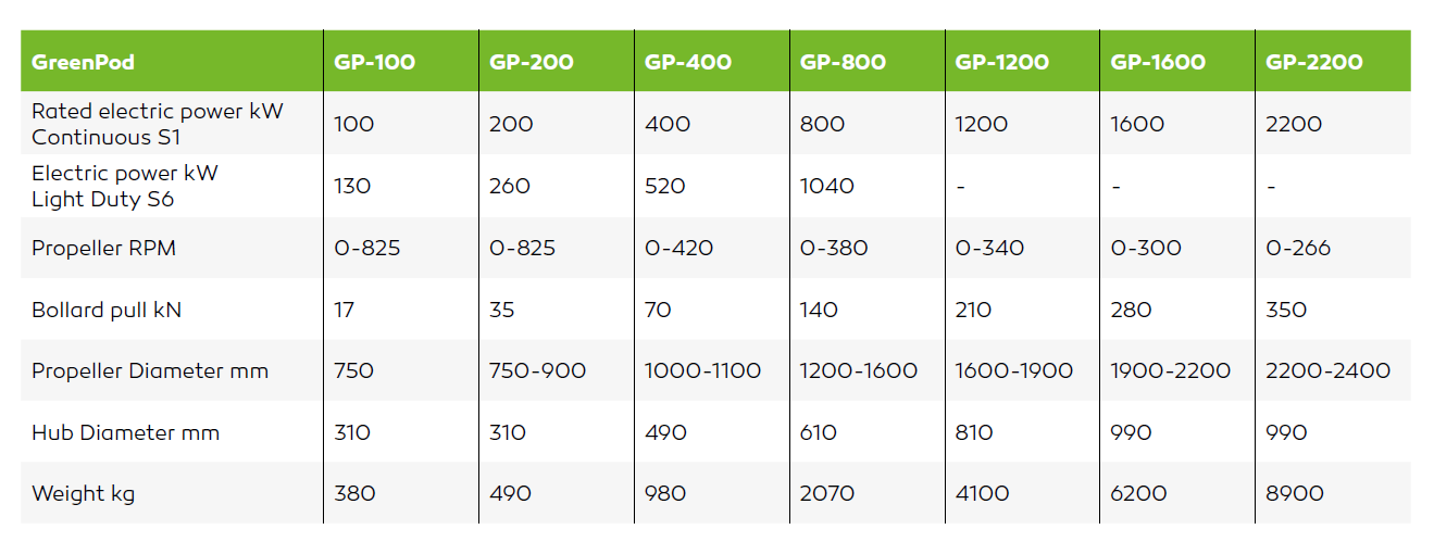
GreenPod is a highly efficient steerable thruster covering propulsion applications from 100kW to 2.2MW. Two versions are available: an electric motor mounted ‘under water’ in line with propeller shaft and a version with a so called L drive with electric motor mounted inside hull on top of the thruster. GreenPod contains a permanent magnet high efficiency electric motor to support a green environment. Up to two electric steering motors provide 360 degrees steering functionality of GreenPod.
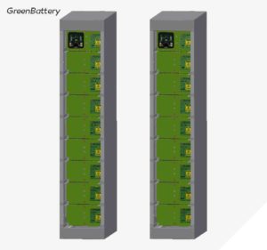
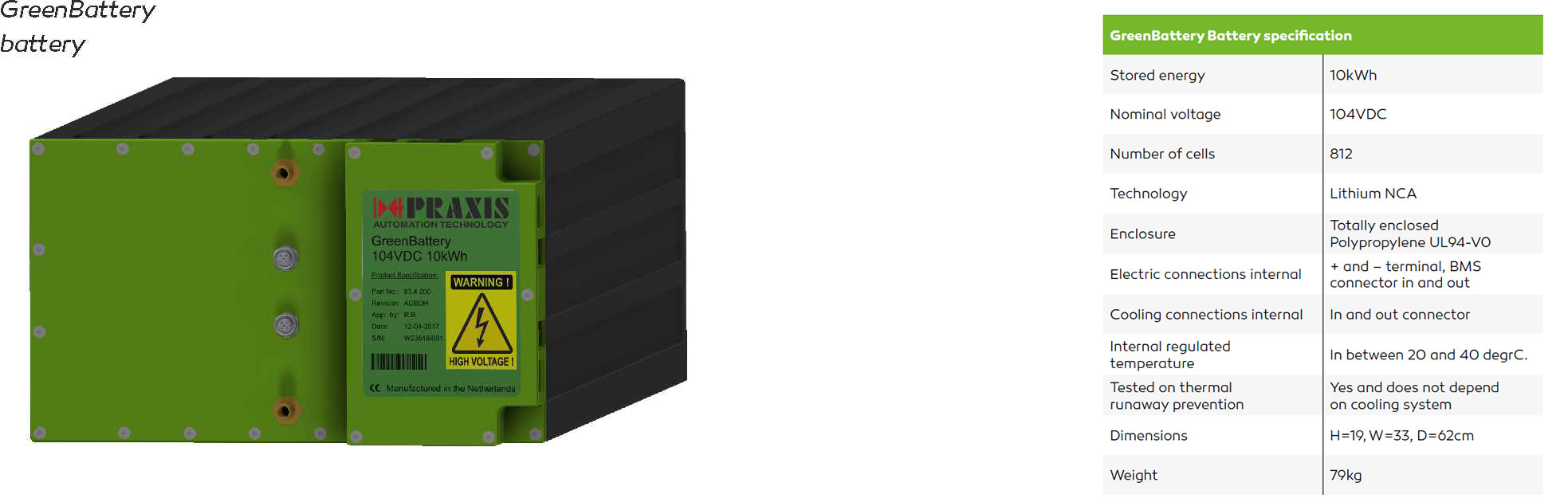
GreenBattery
GreenBattery is a safe, highly efficient and modular energy storage system with relatively low weight and small volume. Each GreenBattery has a capacity of 80kWh and a nominal DC Bus voltage of 832VDC. Multiple GreenBatteries can be mounted in parallel to realize energy storage systems ranging from 80kWh to 4MWh. Each GreenBattery includes a Master BMS and DC Bus contactor. Various safety devices are built into GreenBattery. In the unlikely event of a battery cell explosion, it does not propagate to other cells (no thermal runaway) and it is contained inside the battery housing in order to guarantee a safe energy storage system without pollution to the surrounding environment of GreenBattery.
GreenMotor and GreenGen
GreenMotor electric motor and GreenGen electric generator are highly efficient permanent magnet electrical machines for propulsion and electric power generation. In fact, a GreenMotor can also be used as a GreenGen and vice versa. Low speed versions of GreenMotor are available for direct mounting to a propeller shaft without gearboxes. Medium and high speed versions are available for connecting to third party thrusters and , in case of generator application, to variable speed combustion engines in order to realize a highly efficient generator set to support a green environment.

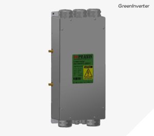
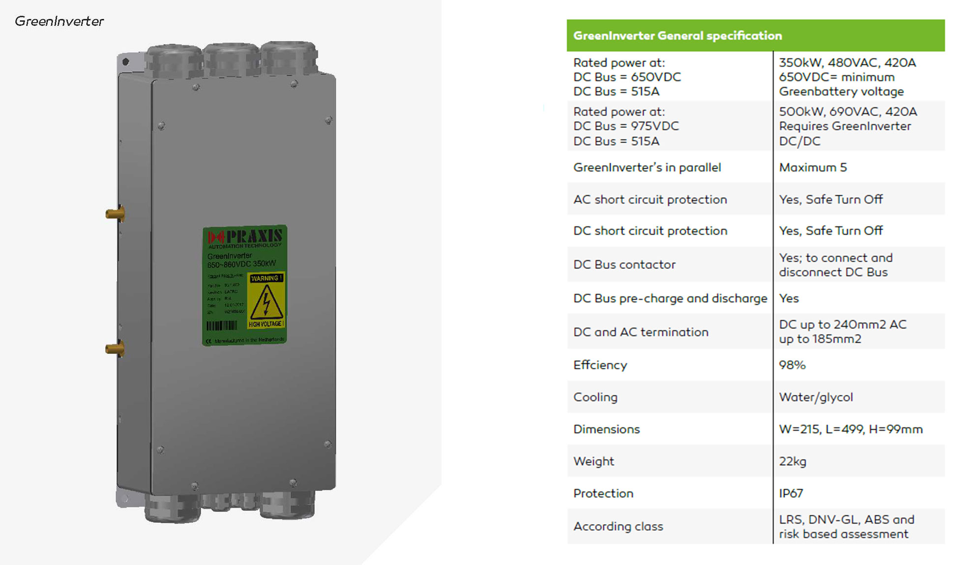
GreenInverter
GreenInverter covers applications for electric motor and generator drive and includes battery charging with GreenGen generators or with shore power. In addition, a GreenInverter AC is available for AC grid generation to support hotel load. GreenInverter is available in power ranges from 100kW to 2.2MW. GreenInverter is connected to the DC Bus with a nominal voltage of 832VDC. A DC Bus contactor and other safety devices are built into each GreenInverter.
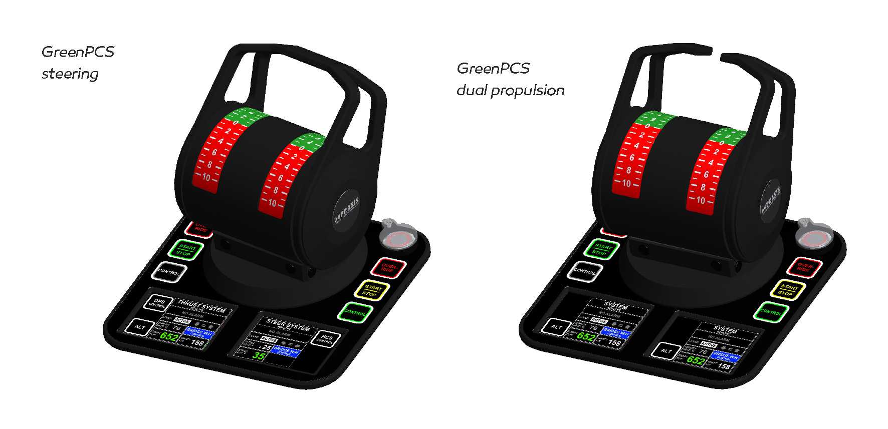
GreenPCS
GreenPCS propulsion control system fully automates the remote control from bridge of the GreenPod or GreenMotor propulsors. In case of parallel hybrid applications; the combustion propulsion engine is controlled as well and automatic change over from electric propulsion motor (low power) to combustion propulsion engine (high power) is fully supported. The GreenPCS propulsion control system also provides steering functions with the application of GreenPod and third party steerable thrusters.
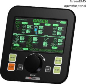
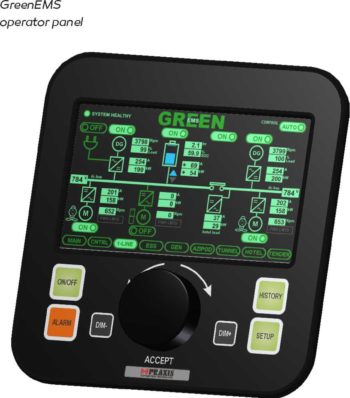
GreenEMS
GreenEMS energy management system allows for automatic energy source selection and control from either the GreenBattery energy banks or GreenGen generator sets. In addition, the energy management system controls the charging of GreenBatteries either by GreenGen generator sets or by shore power.
Applications Green Propulsion
Advantages of electric propulsion
There are two main reasons to change to electric propulsion: zero emissions during electric propulsion and fuel efficiency. Fuel efficiency can be increased with electric propulsion when there is a large difference in operating hours at e.g. cruise speed and maximum speed (or power). The reason for this is that the combustion engine is running only at optimal efficiency when fully loaded; at all other operating points efficiency drops. Electric propulsion when combined with combustion engines realizes that the combustion engine is running at optimal efficiency most of the time, by using the spare power for charging battery packs and/or by switching off one or more combustion engines depending on load requirement. In addition, electric motor propulsion, especially when combined with steerable thrusters, gives a much better maneuverability when compared to combustion propelled vessels as the RPM can be easily controlled from zero to maximum. Some ship applications also require strongly reduced noise emission and this can be realized with the GreenPod steerable thruster as the electric motor is mounted ‘under water’ for optimum noise reduction.
The Mega-Guard Green Propulsion product line covers various propulsion applications which can be summarized as follows:
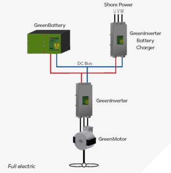
Full electric propulsion
The full electric propulsion uses an electric motor to drive the propeller shaft. Electric power is coming from battery banks and charging is done through shore power. Combustion engines are not installed. With large batteries you can have long periods of electric propulsion and the AC grid for hotel load is generated from the battery bank too. The highly efficient GreenPod steerable thruster perfectly fits into full electric applications.
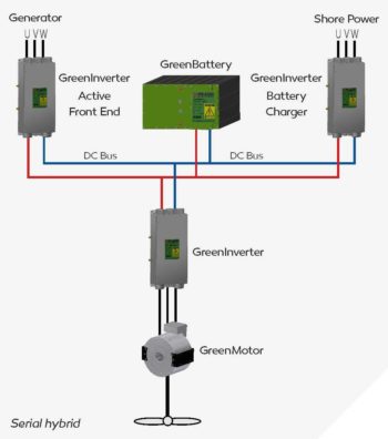
Serial hybrid propulsion
The serial hybrid also uses an electric motor to drive the propeller shaft. Electric power is coming from battery banks or, when battery bank is empty, from a combustion generator set. Charging of the battery bank is done through the combustion generator set or by shore charging. With large batteries you can have long periods of electric propulsion without the need for combustion engines to run as the AC grid for hotel load is generated from the battery bank too. The highly efficient GreenPod steerable thruster perfectly fits into full electric applications.
Parallel hybrid propulsion 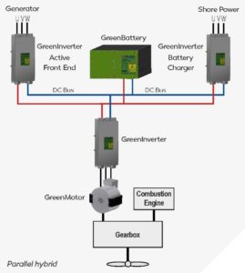
The parallel hybrid propulsion system uses both a combustion engine and an electric motor to drive the propeller shaft. In fact, the combustion engine and the electric motor are mounted in parallel.
Parallel mounting is generally done in one of two ways:
- The propeller shaft from the combustion engine is split in two parts and the electric motor is mounted in between the two shaft parts. This means that the electric motor is mounted in-line with the propeller shaft. The electric motor has also to carry the usually much higher load from the combustion engine. The highly efficient permanent magnet GreenMotor with hollow shaft fits this purpose.
- The electric motor is mounted on an additional input of the gear box which is mounted in between the combustion engine and the propeller shaft.
Parallel hybrid propulsion allows you to drive the propeller shaft by either the electric motor or the combustion engine or by both (boost mode). In case the vessel is propelled by combustion engine, the electric motor acts like a generator which can be used for charging the battery banks.
In case there is a big difference in between operating hours at cruising speed compared with operating hours at maximum speed/power it makes sense to install a parallel hybrid system. The relatively small electric motor can propel the vessel at cruise speed for longer periods. When maximum speed/power is required, the large combustion engine takes over the propulsion and the electric motor is used as generator for charging the batteries. The parallel hybrid has built-in redundancy as the shaft can be driven by either the electric motor or the combustion engine. The highly efficient GreenMotor perfectly fits into parallel hybrid applications.
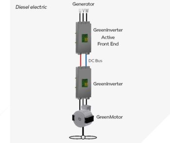
Diesel-electric propulsion
A diesel-electric propulsion system uses generator sets to generate electric power for the electric propulsion motors. The generator sets consist of a combustion engine, which could be gas or diesel, and is connected directly to an electrical generator. The electric propulsion motor is connected directly to the propeller shaft. The diesel electric system usually has multiple generator sets and multiple electric motors connected to a common electrical DC bus. The highly efficient GreenPod steerable thruster and the GreenGen electric generator fits perfectly into diesel-electric applications. Note that there is no electric storage of energy in a diesel electric propulsion application.
GreenPod steerable electric thruster
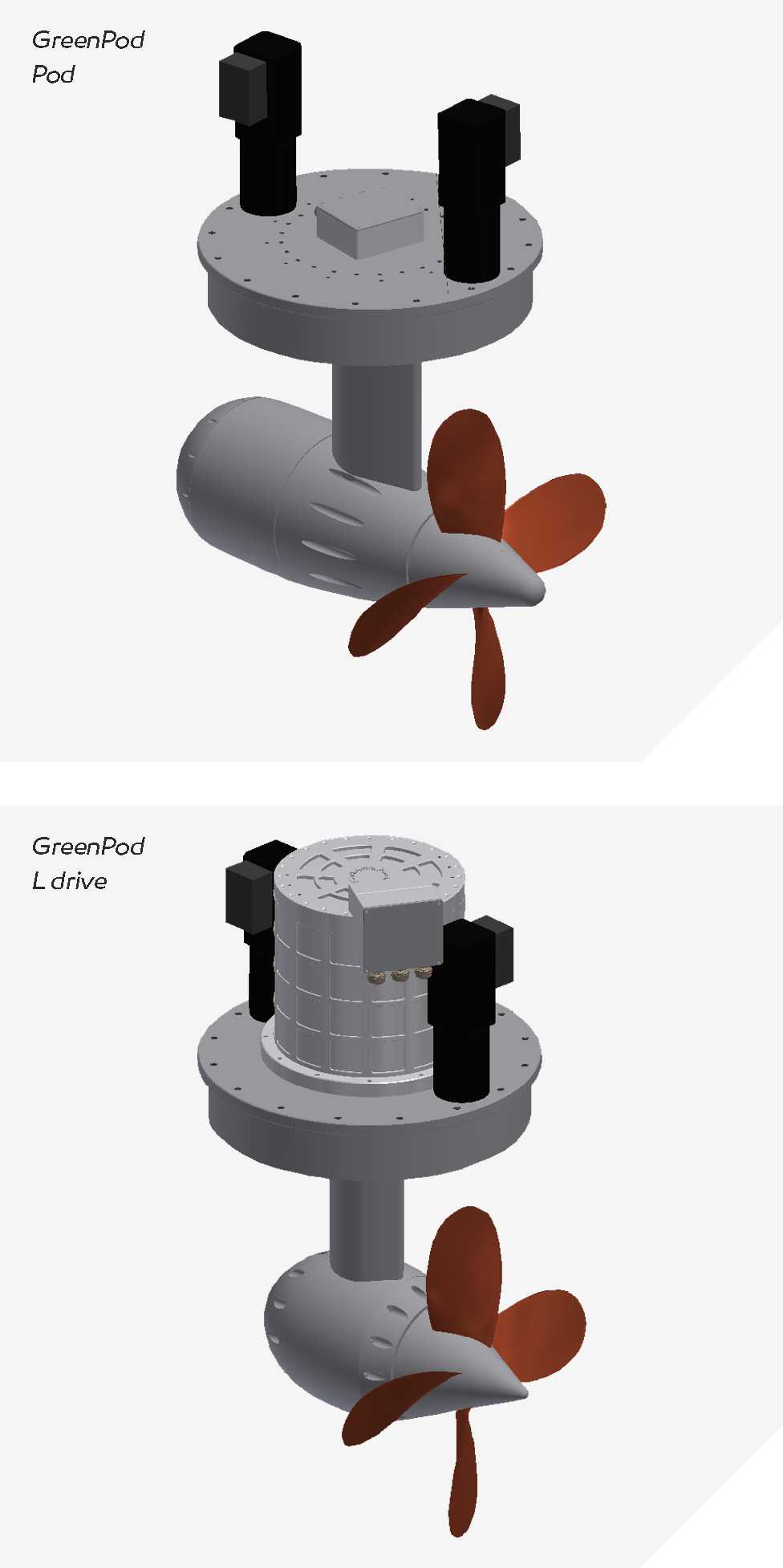
GreenPod steerable electric thruster is designed as a highly efficient fit and forget propulsor that additionally saves a lot of engine room space. In fact, due to its low height GreenPod can be mounted in almost any location.
Two versions are available:
- Pod with electric motor mounted ‘under water’ in line with propeller shaft.
- L drive with electric motor mounted inside hull on top of the L shaped propeller shaft.
GreenPods are available in sizes in between 100kW and 2.2MW. The highly efficient permanent magnet electric motor increases efficiency to support a green environment.
Up to two electric steering motors are mounted on top of GreenPod for reliable and fail safe steering. GreenPod electric propulsion motor is controlled by GreenInverter and the steering motors are controlled by a low power version of GreenInverter. These GreenInverters can be mounted on top of GreenPod for simplified and trouble free installation. GreenInverters are connected directly to DC Bus and to Ethernet communication lines.
Three different propeller configurations can be supplied:
- Pushing : standard configuration up to 12.5 knots
- Dual : propeller contra rotating propellers for speeds above 12.5 knots
- Nozzle : to increase efficiency at speeds below 5 knots to realize highest bollard pull
GreenMotor and GreenGen
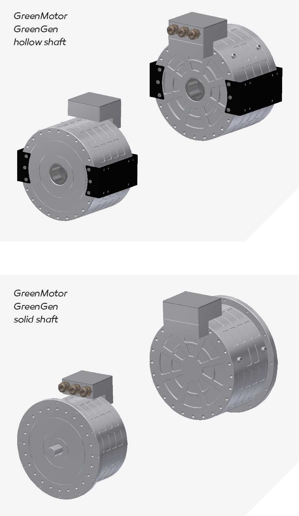
GreenMotor electric motor and GreenGen electric generator are highly efficient permanent magnet electrical machines for propulsion and electric power generation. In fact, a GreenMotor can also be used as a GreenGen and vice versa.
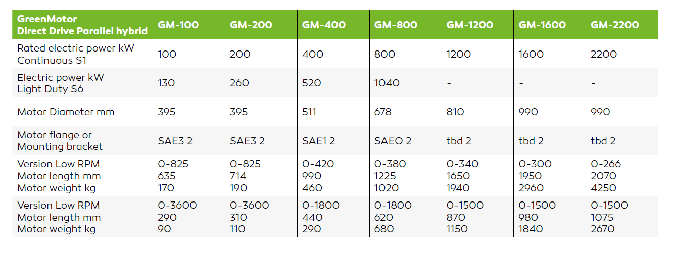
GreenMotor and GreenGen products are available in RPM ranges in between 266 (low speed direct drive of propeller shaft) and 3600 (high speed generator set). GreenMotor and GreenGen can be either flange or bracket mounted. In addition, customer can choose between hollow shaft or solid shaft on one side or on both sides of the machine. In case of parallel hybrid applications, the low speed GreenMotor can be connected to the propeller shaft on one side and the other side can be connected to the output shaft of gearbox. Versions of GreenGen are available for direct mounting on flywheel housing of several models diesel engines from Cummins, Volvo, Steyr and Hyundai.
Flange mounting connections, vibration damping plates and other specifications can easily be adapted to accommodate other combustion engines. GreenMotor and GreenGen are cooled by water cooling (50% water/50% glycol). Each GreenMotor and GreenGen is controlled by a GreenInverter which is connected to DC Bus of nominal 832VDC.
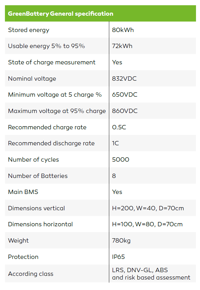
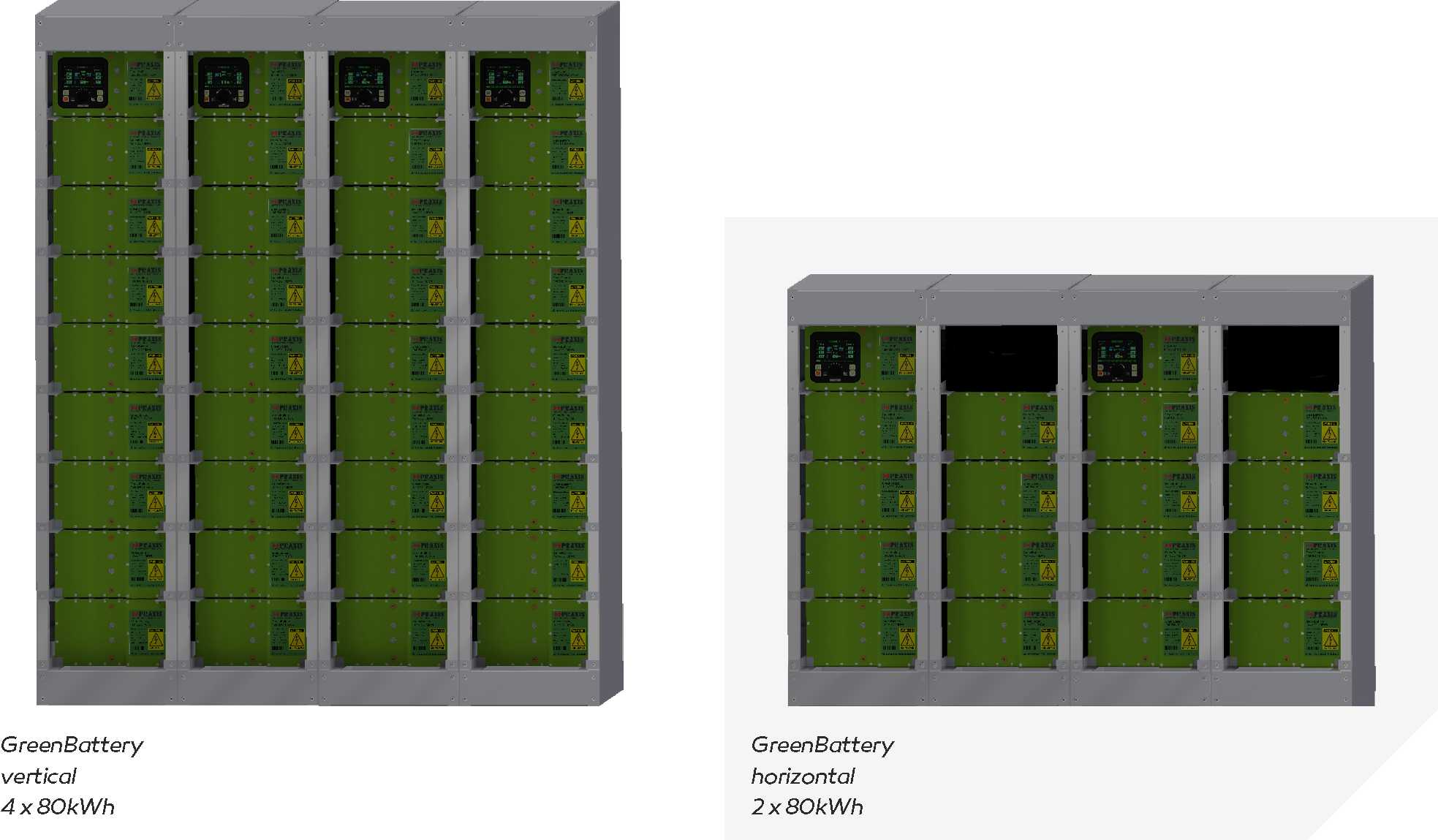
GreenBattery is a highly efficient and modular energy storage system with relatively low weight and small volume. Each GreenBattery has a capacity of 80kWh and a nominal DC Bus voltage of 832VDC. Multiple GreenBatteries can be mounted in parallel to realize energy storage systems ranging from 80kWh to 4MWh.
Each GreenBattery is built up with 8 individual batteries and a Master BMS. The Master BMS contains a 5”TFT operator panel with controller and includes a DC Bus contactor and heat exchanger. All external connections are made available on the Master BMS.
Various safety devices are built-in for preventing thermal runaway. In the unlikely event of a battery cell explosion, it is contained inside the battery housing in order to guarantee a safe energy storage system without pollution to the surrounding environment of GreenBattery. Each battery is totally enclosed and GreenBattery includes a pressure based safety release which should be vented to the outside environment.
GreenBattery is liquid cooled by seawater or water/glycol and a built-in controller regulates battery temperature in between 20 and 40 degrC. GreenBattery can be placed in any room with the ambient temperature up to 55 degrC. GreenBattery does not heat-up the room.
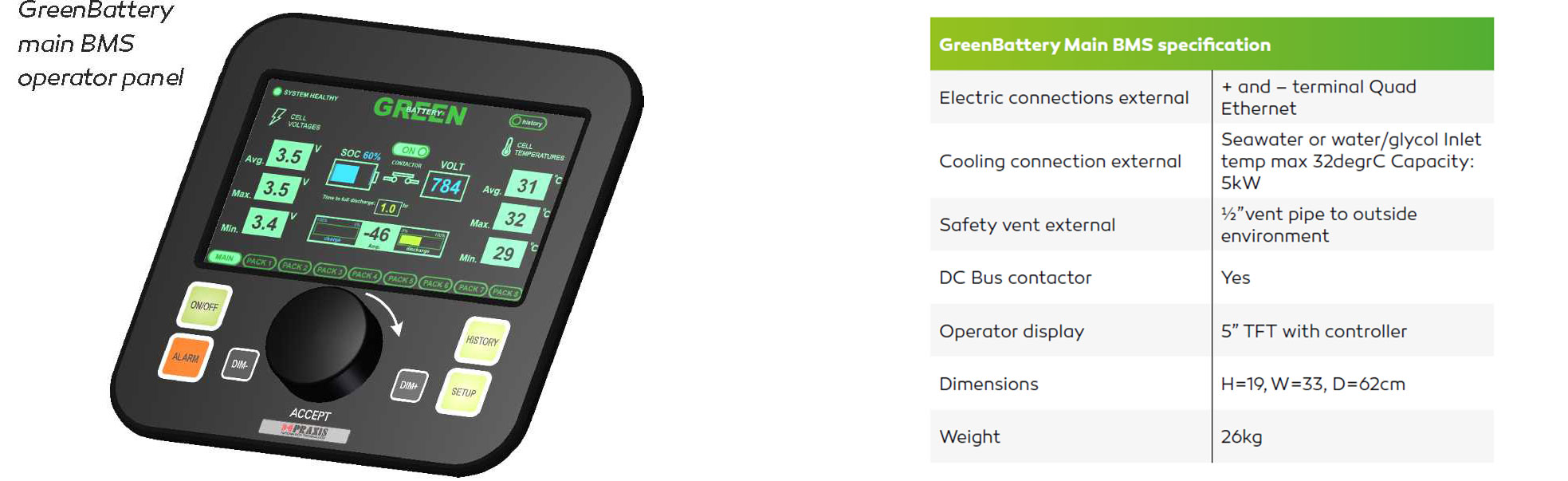
Battery management 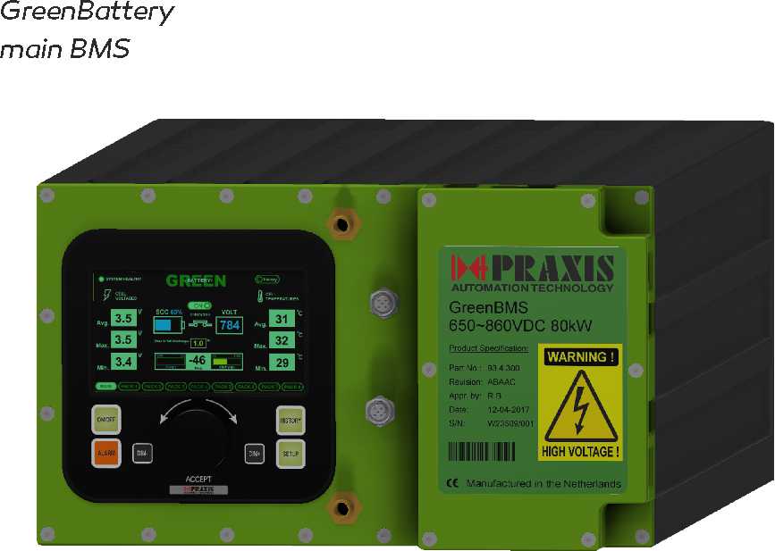
The batteries are built up with Lithium NCA technology battery cells which have considerable lower weight and higher power density when compared to other battery chemistries. In addition the applied Panasonic battery cells have a long track record and are widely used in electric cars. Each battery has 12 temperature measurements and a built-in BMS (Battery Management System) which communicates with the Main BMS. The Main BMS 5”TFT operator panel contains redundant Ethernet ports for communication to GreenInverters for charging/discharging and GreenEMS for energy management. GreenBattery fulfils the latest class requirements and a risk based assessment is made for every project and approved by class. GreenBattery is supplied in two different mechanical lay-outs: a vertical one for space saving and a horizontal one
with a lower center of gravity.
GreenInverter high power inverter
GreenInverter is designed to be installed close to the device to be controlled for distributed DC Bus applications. However, centralized installation of GreenInverter is supported as well. GreenInverter is built-up with two controllers: a dedicated Digital Signal Processor for four quadrant motor and generator control functions and a Control Processor with four Ethernet ports for programming PLC functions in accordance with IEC61131 standard. Input and output signals (including J1939/NMEA2000) of e.g. GreenPod and combustion engines with GreenGen can be directly connected and controlled by GreenInverter.
GreenInverter is also available for following:
- DC/DC conversion :GreenInverter DC/DC
- AC grid generation :GreenInverter AC
These GreenInverters are based upon the standard GreenInverter and extended with magnetics. In addition, a low power GreenInverter LP is available for e.g. steering motor and bow thruster.
GreenInverter covers applications for electric motor and generator drive and includes battery charging with GreenGen generators or shore power as well. GreenInverter is built-up in a modular way, supporting applications from 100kW to 2.2MW. GreenInverter is a four quadrant controller with active front end technology. Motor operation changes into generator operation as soon as a motor is driven by propeller (brake energy) or combustion engine (parallel hybrid). The generated energy is used for GreenBattery charging.
GreenInverter includes independent safety systems such as Safe Torque Off on AC side and contactor on DC side for connecting and disconnecting the DC Bus from GreenInverter. The contactor also supports pre-charging and discharging in order to safely connect and disconnect GreenInverter from DC Bus. GreenInverter is optimized for DC Bus voltages in between 650VDC and 975VDC and a nominal current up to 450A. This results in a rated power range from 350kW to 500kW. Multiple GreenInverters can be paralleled to increase the power up to 2.2MW. GreenInverter is IP67 protected and can be bulkhead mounted.
GreenEMS and GreenPCS
Energy Management
GreenEMS energy management system allows for automatic energy source selection from either the GreenBattery energy banks or GreenGen generator sets. In addition, the energy management system controls the charging of GreenBatteries either by GreenGen or by shore power.
GreenEMS includes a 5” TFT operator panel on which all data regarding consumers (GreenPod’s, GreenBattery charging and hotel load) and producers (GreenGens and GreenBatteries discharging) are available. Mode selection pushbuttons are available as well on GreenEMS 5”TFT operator panel. GreenEMS contains a project specific control strategy in order to control the consumers and producers.
GreenEMS communicates to GreenInverter, GreenBattery and GreenPCS through redundant Ethernet communication ports to monitor and command these devices. As all Green products are built-up from the same technology, a transparent and trouble free control strategy can be implemented in standard IEC61131 language.
Propulsion Control System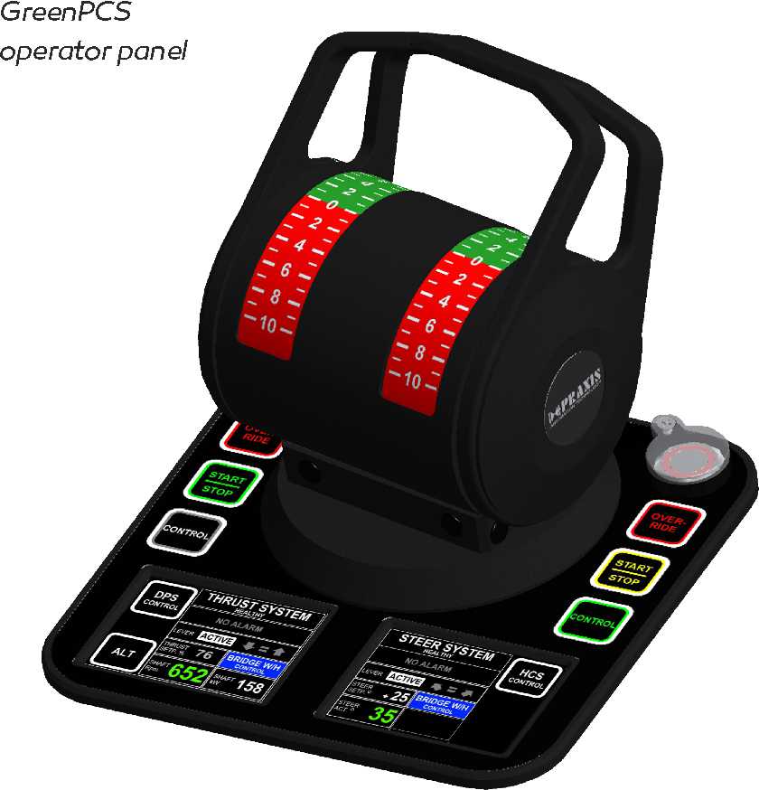
GreenPCS propulsion control system fully automates remote control from the bridge of GreenPod or GreenMotor propulsors. In case of parallel hybrid applications, the combustion propulsion engine is controlled as well and automatic change over from electric propulsion motor (low power) to combustion propulsion engine (high power) is fully supported.
The GreenPCS propulsion control system provides steering functions with the application of GreenPod and third party steerable thrusters. The GreenPod azimuth lever includes two 2.5”TFT display panels and operator pushbuttons for mode selection. They can be supplied including electrical shaft for synchronous operation. GreenPCS can also be applied for thrusters without steering function. In this case, typically a GreenPod dual lever with two 2.5”TFT displays and two rows of operator pushbuttons is supplied to independently operate the port and starboard side GreenMotor.
GreenPCS operator modes are adapted for every application. An example functionality is given below with two GreenPod steerable thrusters:
- Individual mode
- Combined mode
- Autopilot mode with Mega-Guard HCS
- DP auto mode with Mega-Guard DP
- + Overview
-
System Overview
HMA – PATEC Integrated Control and Management System (ICMS) is a highly versatile and dependable ship automation solution providing a coherent, user-friendly interface to virtually all the subsystems of modern vessels. Designed to meet the demands of contemporary navigation, the HMA – PATEC Integrated Control and Management System is an ideal solution both for newly-built ships, and for in-operation ships needing an upgrade.
In its standard configuration, HMA – PATEC ICMS provides the following components:
- Alarm and Monitoring System (AMS)
- Extension Alarm System (EAS)
- Power Management System (PMS)
- Cargo Control and Monitoring System (CCMS)
- Anti-Heeling System (AHS)
Features
The key features that define the HMA – PATEC Integrated Control and Management System (ICMS) and distinguish it from other ship automation solutions are:
- FLEXIBILITY – The HMA – PATEC ICMS encompasses several subsystems (HMA – PATEC Alarm and Monitoring System, HMA – PATEC Power Management System, HMA – PATEC Cargo Control and Monitoring System, HMA – PATEC Anti-Heeling System) which can be integrated in a variety of configurations and can even work as stand-alone systems. The component-oriented design, together with the support of an extensive array of communicating protocols, enables HMA – PATEC systems to be integrated with existing third-party systems in a timely and cost-effective manner.
- RELIABILITY – The components of the HMA – PATEC ICMS were designed to operate as distributed software systems communicating on redundant networks and supervised by redundant process controllers. This No-Single-Point-of-Failure architecture, backed by the use of rugged, industrial-grade hardware components, has turned the HMA – PATEC ICMS into one of the most dependable systems in the field today.
- CONSISTENCY – All HMA – PATEC ICMS systems share a standard set of hardware components, a common software development framework, and characteristic Graphical User Interface elements. The system’s orthogonal structure reduces production and maintenance costs and facilitates a fast learning curve for developers, commissioning agents, and operators.
Hardware Architecture
Through distribution and segregation, the consequences of a system fault are reduced and may even be eliminated. In order to achieve high availability, the PATEC Integrated Control and Management System executes its control, alarm and monitoring functions on several independent processing nodes, in a client-server architecture. These nodes, called Distributed Processing Units (DPU), are typically located close to the ship’s sensors and actuators (in order to minimize cabling), and are made-up of:
- I/O Modules, connected directly to the sensors and actuators and mounted on DIN rails; their main purpose is to acquire data from sensors, or convey commands to actuators, but they also offer data processing capabilities for fast response to time-critical input events;
- Serial Communications Links for communications with external machinery or third-party control systems (e.g., main engines, navigation equipment, voyage data recorder, etc.); the HMA – PATEC ICMS supports an extensive number of standard serial communications protocols;
- Control Processors, using the data acquired from the I/O modules or serial links to execute the control logic; the control processors can communicate with up to 8 I/O modules over a redundant fieldbus network (CAN-Bus), and can also communicate with other control processors over a redundant Ethernet network. Optional hot standby processors can be used to enhance the availability and security of critical applications. A control processor uses a 32-bit Intel microprocessor and can control up to 544 I/O channels. A HMA – PATEC ICMS system can accommodate up to 96 control processors, providing a maximum of 52,224 I/O channels.
The Distributed Processing Units are fully-fledged stand-alone systems that meet classification requirements, but the interaction with the operators is limited. Extensive user interaction with the HMA – PATEC ICMS is accomplished by:
Operator Panels, connected to Control Processors or to specialized I/O Modules, which may be equipped with LCD displays. The Operator Panels can be tailored to the owner’s specific needs, but a considerable number of specialized ones are readily available, such as:
Workstations running the extremely intuitive HMA – PATEC ICMS software, allowing operators to fully interact with the system. For safety reasons, the standard configuration comprises two workstations working in parallel (Main and Backup), further enhancing the reliability of the system. A typical workstation is driven by the Windows XP Operating System and consists of:
- Industrial-grade, rugged Personal Computers equipped with solid-state disks (no moving parts);
- TFT flat screen;
- Operator Keyboard or Trackball;
- Printer.
Software Design
HMA – PATEC ICMS software displays a series of unique features, chief among them being its open nature: unlike other products in the ship automation industry, HMA – PATEC software does not require a license or an authorization key, nor do we impose any temporal limit upon the customers’ right to use the binary or source code.
In order to achieve greater development efficiency and software reliability, HMA – PATEC ICMS provides a development framework, distributed with any purchased system. Using this highly intuitive development framework, customers can easily parameterize or update the software whenever the circumstances require it, without any additional costs. Such modifications can be operated while the system is running, since the development framework will automatically download the modified code into the target control processor over the network, thus eliminating cumbersome and error-prone manual updates.
The HMA – PATEC ICMS development framework is integrated with a graphical user interface editor. Thus, existing mimics can be easily modified by the operators (no programming background is required), linked to the target I/O channels and imported back into the system without any additional fees. Once again, such modifications do not require a system shutdown – they can be performed online, and the development framework will automatically perform the necessary update steps.
Joining the latest trend in PLC programming systems, the HMA – PATEC ICMS development framework uses IEC 1131 – a high-level, standardized programming language. The use of IEC 1131 reduces development costs, increases software reliability and portability, and allows the implementation of more complex programming systems. From the owners’ perspective, a standardized programming language eliminates the risk of customer lock-in and opens up alternative paths.
Offering unrivaled flexibility, functionality, life cycle support and user-friendliness, the PATEC ICMS development framework furthers safe and efficient development, reduces the overall costs of ownership, and is scalable to suit individual customer needs.
- + AMS
-
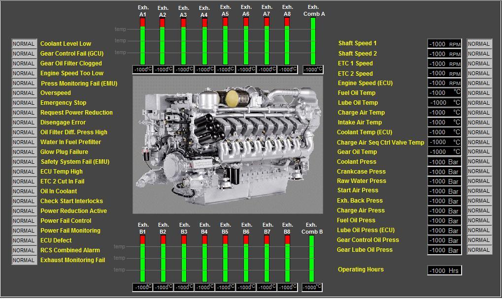
The HMA – PATEC Alarm and Monitoring System (AMS) represents the core functionality of the HMA – PATEC Integrated Control and Management System. The main purpose of the system is to give ship’s officers all the basic alarm and status information they require to maintain safe and efficient operation of the machinery and other related equipment. The HMA – PATEC AMS is the perfect automation solution for medium-sized and large vessels, as all the ship”s machinery and other subsystems can be monitored and remotely operated from the redundant operator workstations.
All analog and digital sensors / actuators can be directly connected to standard HMA – PATEC Distributed Processing Units, while the main and auxiliary engines, as well as other third-party systems, can be interfaced to the HMA – PATEC AMS through serial communications links, and monitored from the high-resolution mimic diagrams.
Alarms and other information are presented either as lists, or as graphic displays on the operator workstations. To record alarms and events a number of different logging options are available including complete log, alarm log, group log, etc.
The main features and benefits of HMA – PATEC Alarm & Monitoring Systems are:
- Alarm detection (with visual and acoustic alarm indication) and alarm inhibit;
- Fast and consistent response time to abnormal conditions;
- Filtering and suppression of spurious alarms;
- Logging of alarms and events to printer;
- Alarm groups, summary and history;
- Trend and performance monitoring;
- Exhaust gas temperature monitoring;
- Tanks gauging and monitoring;
- Automated fuel oil transfer;
- Intuitive graphic presentation of ship subsystems;
- Reduced risk of human error and enhanced operational efficiency;
- Operational access limited by command control and password protection;
- Built-in self-diagnostic system;
- Easy integration of other systems and free flow of information from all subsystems.
Based on a modular and scalable concept, the HMA – PATEC AMS may easily be extended by adding additional hardware units such as operator workstations, control processors and I/O modules. Consequently, PATEC AMS functionality may be updated with minimum costs and enhanced to suit ever-changing individual customer needs.
Owing to the state-of-the-art technology used, HMA – PATEC AMS is comprehensive, secure, scalable, integrated and completely reliable. It furthers safe and efficient operations, reduces the overall costs of ownership, and represents the ideal solution for both present and future customer needs.
- + EAS
-
The Extension Alarm System (EAS) is a highly reliable engineer calling system, which extends PATEC Automation System for unmanned machinery space operation and provides the following functions:
- On Duty Selection;
- Attended / Unattended Engine Room indication and/or selection;
- Engineer Calling;
- Patrol timer / engineer safety system (dead man timer).
The On Duty Selection and Engineer Calling functions are executed on a dedicated mimic diagram on the operator workstation and are fully redundant (upon workstation failure, the extension alarm system functions are automatically transferred to a back-up workstation).
Custom-designed EAS Operator Panels equipped with a redundant Ethernet link for communication to the workstations are installed in bridge and accommodation areas (e.g., in cabins). These panels have the following characteristics:- 8 lines / 40 character LCD display for displaying individual alarms
- On Duty lamp
- 8 Group Alarm lamps with buzzer
- Fire Alarm lamp with buzzer
- Call ECR and Call Bridge pushbuttons
- Accept and Stop Horn pushbuttons
- Dimming pushbuttons
The graphic display of the operator panel is also used for manually programming the panel during installation. The programmed data can be stored in the panel’s memory, or it can be loaded via a USB memory stick. The redundant Ethernet link is also used for sending the dimming level settings to other panels, in order to synchronize the dimming level on bridge.
The following hardware inputs and outputs are used by the Extension Alarm System:
Input Output
Attended
Unattended
Patrol Alarm Timer Pre-Warning
Reset Patrol Alarm Timer
Patrol Alarm Timer Off
General Engineers Alarm
Dead Man Alarm
Horn Activation
Stop Horn
System Failure - + PMS
-
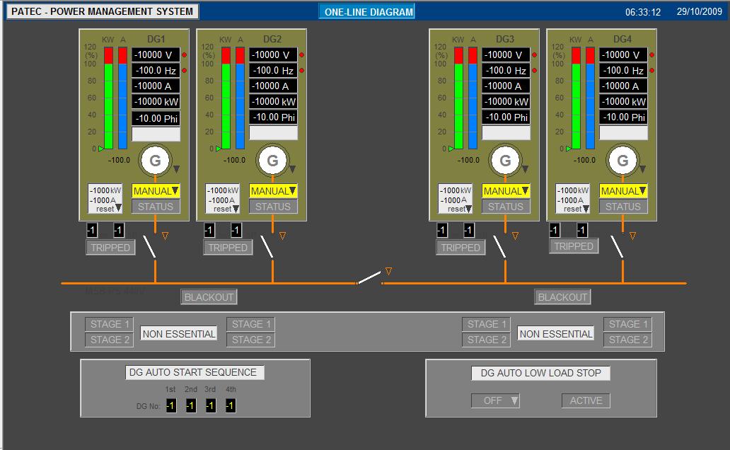
HMA – PATEC Power Management System (PMS) is an advanced system for full automation of power plants, including power management, diesel engine control, generator control, generator protection and optional diesel engine safety system. Each generator set is equipped with its own independent and autonomous PMS system. This ensures the highest degree of reliability and availability. The PMS is supplied as a complete product and no additional components are needed for automation of a low voltage switchboard up to 690VAC.
For each generator set, the PMS is implemented with specialized I/O modules which contain inputs and outputs to connect to the diesel engine, generator, busbar and main circuit breaker. The generator set is operated either from a PMS panel (equipped with a user-friendly graphic display for read-out of power plant parameters), or from the workstations, through dedicated mimic diagrams.
The HMA – PATEC PMS is a fully automatic system, but can also be operated in a semi-automatic mode (by using the pushbuttons on the operator panel), and offers the following functions:
A) Auto Mode
B) Semi-Auto Mode
In addition, the PMS for a shaft generator or shore connection provides the following supplementary functions:
- Automatic synchronization of the shaft/shore supply with load transfer of diesel generators to shaft/shore and disconnect the running diesel generators;
- Automatic start and synchronization of diesel generators with load transfer from shaft/shore supply and disconnect the shaft supply.
- + CCMS
-
The HMA – PATEC Cargo Control & Monitoring System (CCMS) fully automates the control of ballast systems, as well as the loading and unloading of product tankers and chemical carriers. Automatic control is fully transparent to operator who can smoothly take manual control at any time.
The cargo console is typically equipped with several workstations (touch screen capabilities are optional) which allow the monitoring and control of ballast/cargo tanks, pumps, and valves through interactive graphic mimic overviews of the target system.
The main functions of the HMA – PATEC Cargo Control & Monitoring System are:
A) Tank Gauging and Monitoring
Using measurements from sensors or radar level measurement systems, the HMA – PATEC software monitors the contents of each tank and displays the following data:
The interfacing with the level measurement system is accomplished by:
B) Valves and Pumps Control
Standard HMA – PATEC control processors and I/O modules control the cargo and ballast pumps and valves. Pumps and valves actuators are wired directly to the I/O modules. The control processors execute either the pre-programmed automatic loading or unloading algorithms, or the commands issued by the operator through the agency of interactive mimic diagrams.
Offering full hardware and software redundancy, the HMA – PATEC CCMS is the ideal choice for ballast/cargo monitoring and can be integrated with any third-party Loading Computer software in order to calculate the shear forces and bending moments, the actual/required stability and the damage stability calculations.
- + Green Propulsion
-
Introduction
Praxis Automation Technology BV has extended the Mega-Guard product range with a new concept for Green Propulsion in order to show our commitment to environmental friendly propulsion of ships. We provide a total in-house developed and manufactured electric and hybrid propulsion solution for shipowners and shipyards who care about the environment and on-board safety. The following applications are covered by Mega-Guard Green Propulsion:
- Full electric: Battery power and electric motor
- Diesel electric: Generator power and electric motor
- Serial hybrid: Battery plus generator power and electric motor
- Parallel hybrid: Battery plus generator power. Shaft driven by electric motor and/or combustion engine
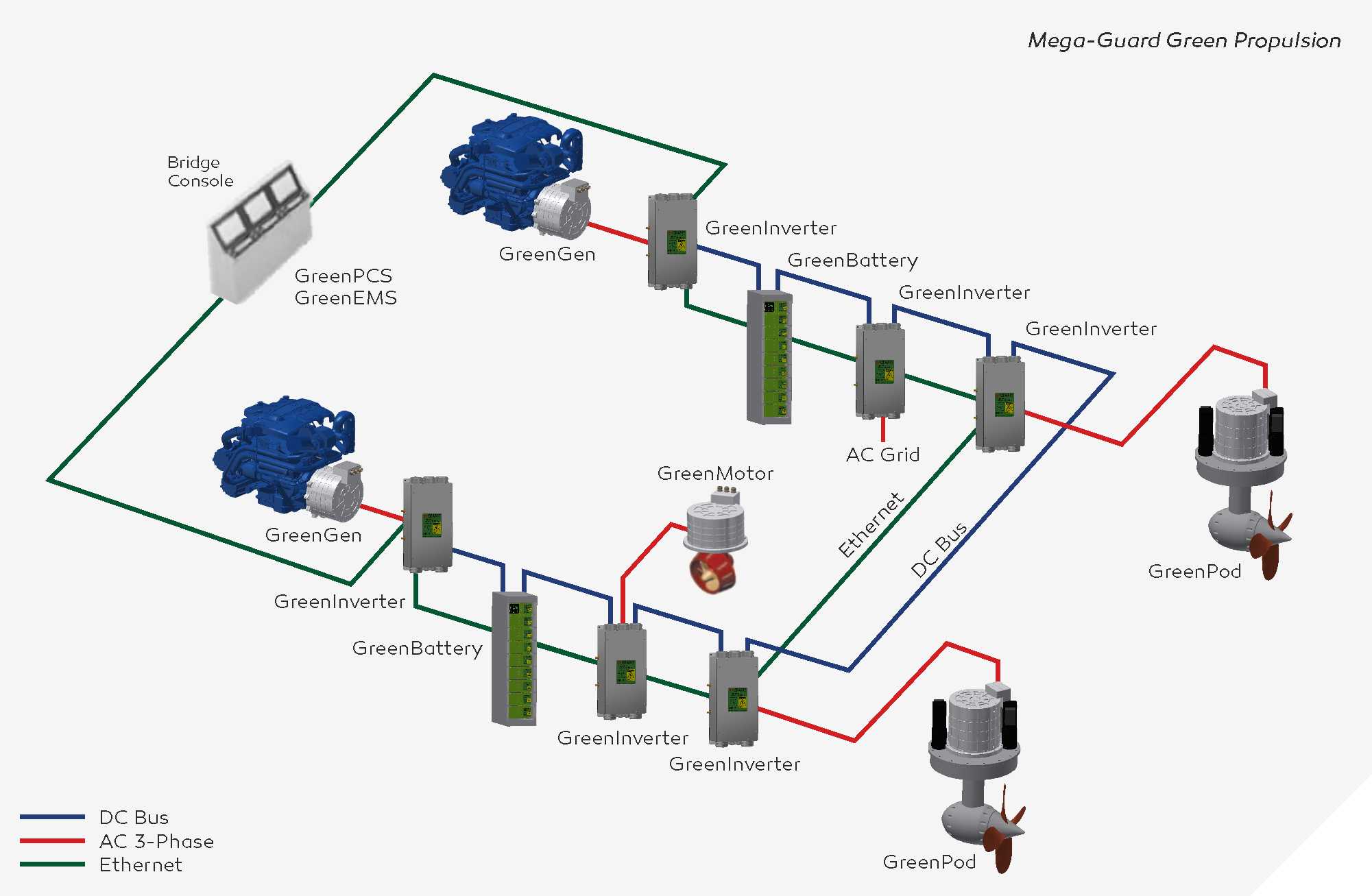
The backbone of Mega-Guard Green Propulsion is the energy distribution with an highly efficient DC Bus and communication between the different Green Propulsion products with redundant Ethernet. As for all Mega-Guard products, Mega-Guard Green Propulsion is supported by a worldwide service network and comes with a guaranteed availability of spare parts and support of 20 years as a minimum. All Mega-Guard products are designed to the highest standards of safety and are class approved by all major classification societies. Mega-Guard Green Propulsion can be further extended with other Mega-Guard products such as Heading Control, Dynamic Positioning and Control, Alarm and Monitoring systems.
Green Propulsion product summary
The Mega-Guard Green Propulsion product line is built-up with the following main products:
GreenPod
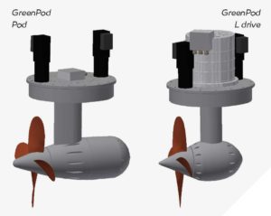
GreenPod is a highly efficient steerable thruster covering propulsion applications from 100kW to 2.2MW. Two versions are available: an electric motor mounted ‘under water’ in line with propeller shaft and a version with a so called L drive with electric motor mounted inside hull on top of the thruster. GreenPod contains a permanent magnet high efficiency electric motor to support a green environment. Up to two electric steering motors provide 360 degrees steering functionality of GreenPod.
GreenBattery
GreenBattery is a safe, highly efficient and modular energy storage system with relatively low weight and small volume. Each GreenBattery has a capacity of 80kWh and a nominal DC Bus voltage of 832VDC. Multiple GreenBatteries can be mounted in parallel to realize energy storage systems ranging from 80kWh to 4MWh. Each GreenBattery includes a Master BMS and DC Bus contactor. Various safety devices are built into GreenBattery. In the unlikely event of a battery cell explosion, it does not propagate to other cells (no thermal runaway) and it is contained inside the battery housing in order to guarantee a safe energy storage system without pollution to the surrounding environment of GreenBattery.
GreenMotor and GreenGen
GreenMotor electric motor and GreenGen electric generator are highly efficient permanent magnet electrical machines for propulsion and electric power generation. In fact, a GreenMotor can also be used as a GreenGen and vice versa. Low speed versions of GreenMotor are available for direct mounting to a propeller shaft without gearboxes. Medium and high speed versions are available for connecting to third party thrusters and , in case of generator application, to variable speed combustion engines in order to realize a highly efficient generator set to support a green environment.
GreenInverter
GreenInverter covers applications for electric motor and generator drive and includes battery charging with GreenGen generators or with shore power. In addition, a GreenInverter AC is available for AC grid generation to support hotel load. GreenInverter is available in power ranges from 100kW to 2.2MW. GreenInverter is connected to the DC Bus with a nominal voltage of 832VDC. A DC Bus contactor and other safety devices are built into each GreenInverter.
GreenPCS
GreenPCS propulsion control system fully automates the remote control from bridge of the GreenPod or GreenMotor propulsors. In case of parallel hybrid applications; the combustion propulsion engine is controlled as well and automatic change over from electric propulsion motor (low power) to combustion propulsion engine (high power) is fully supported. The GreenPCS propulsion control system also provides steering functions with the application of GreenPod and third party steerable thrusters.
GreenEMS
GreenEMS energy management system allows for automatic energy source selection and control from either the GreenBattery energy banks or GreenGen generator sets. In addition, the energy management system controls the charging of GreenBatteries either by GreenGen generator sets or by shore power.
Applications Green Propulsion
Advantages of electric propulsion
There are two main reasons to change to electric propulsion: zero emissions during electric propulsion and fuel efficiency. Fuel efficiency can be increased with electric propulsion when there is a large difference in operating hours at e.g. cruise speed and maximum speed (or power). The reason for this is that the combustion engine is running only at optimal efficiency when fully loaded; at all other operating points efficiency drops. Electric propulsion when combined with combustion engines realizes that the combustion engine is running at optimal efficiency most of the time, by using the spare power for charging battery packs and/or by switching off one or more combustion engines depending on load requirement. In addition, electric motor propulsion, especially when combined with steerable thrusters, gives a much better maneuverability when compared to combustion propelled vessels as the RPM can be easily controlled from zero to maximum. Some ship applications also require strongly reduced noise emission and this can be realized with the GreenPod steerable thruster as the electric motor is mounted ‘under water’ for optimum noise reduction.
The Mega-Guard Green Propulsion product line covers various propulsion applications which can be summarized as follows:
Full electric propulsion
The full electric propulsion uses an electric motor to drive the propeller shaft. Electric power is coming from battery banks and charging is done through shore power. Combustion engines are not installed. With large batteries you can have long periods of electric propulsion and the AC grid for hotel load is generated from the battery bank too. The highly efficient GreenPod steerable thruster perfectly fits into full electric applications.
Serial hybrid propulsion
The serial hybrid also uses an electric motor to drive the propeller shaft. Electric power is coming from battery banks or, when battery bank is empty, from a combustion generator set. Charging of the battery bank is done through the combustion generator set or by shore charging. With large batteries you can have long periods of electric propulsion without the need for combustion engines to run as the AC grid for hotel load is generated from the battery bank too. The highly efficient GreenPod steerable thruster perfectly fits into full electric applications.
Parallel hybrid propulsion
The parallel hybrid propulsion system uses both a combustion engine and an electric motor to drive the propeller shaft. In fact, the combustion engine and the electric motor are mounted in parallel.
Parallel mounting is generally done in one of two ways:
- The propeller shaft from the combustion engine is split in two parts and the electric motor is mounted in between the two shaft parts. This means that the electric motor is mounted in-line with the propeller shaft. The electric motor has also to carry the usually much higher load from the combustion engine. The highly efficient permanent magnet GreenMotor with hollow shaft fits this purpose.
- The electric motor is mounted on an additional input of the gear box which is mounted in between the combustion engine and the propeller shaft.
Parallel hybrid propulsion allows you to drive the propeller shaft by either the electric motor or the combustion engine or by both (boost mode). In case the vessel is propelled by combustion engine, the electric motor acts like a generator which can be used for charging the battery banks.
In case there is a big difference in between operating hours at cruising speed compared with operating hours at maximum speed/power it makes sense to install a parallel hybrid system. The relatively small electric motor can propel the vessel at cruise speed for longer periods. When maximum speed/power is required, the large combustion engine takes over the propulsion and the electric motor is used as generator for charging the batteries. The parallel hybrid has built-in redundancy as the shaft can be driven by either the electric motor or the combustion engine. The highly efficient GreenMotor perfectly fits into parallel hybrid applications.
Diesel-electric propulsion
A diesel-electric propulsion system uses generator sets to generate electric power for the electric propulsion motors. The generator sets consist of a combustion engine, which could be gas or diesel, and is connected directly to an electrical generator. The electric propulsion motor is connected directly to the propeller shaft. The diesel electric system usually has multiple generator sets and multiple electric motors connected to a common electrical DC bus. The highly efficient GreenPod steerable thruster and the GreenGen electric generator fits perfectly into diesel-electric applications. Note that there is no electric storage of energy in a diesel electric propulsion application.
GreenPod steerable electric thruster
GreenPod steerable electric thruster is designed as a highly efficient fit and forget propulsor that additionally saves a lot of engine room space. In fact, due to its low height GreenPod can be mounted in almost any location.
Two versions are available:- Pod with electric motor mounted ‘under water’ in line with propeller shaft.
- L drive with electric motor mounted inside hull on top of the L shaped propeller shaft.
GreenPods are available in sizes in between 100kW and 2.2MW. The highly efficient permanent magnet electric motor increases efficiency to support a green environment.
Up to two electric steering motors are mounted on top of GreenPod for reliable and fail safe steering. GreenPod electric propulsion motor is controlled by GreenInverter and the steering motors are controlled by a low power version of GreenInverter. These GreenInverters can be mounted on top of GreenPod for simplified and trouble free installation. GreenInverters are connected directly to DC Bus and to Ethernet communication lines.
Three different propeller configurations can be supplied:- Pushing : standard configuration up to 12.5 knots
- Dual : propeller contra rotating propellers for speeds above 12.5 knots
- Nozzle : to increase efficiency at speeds below 5 knots to realize highest bollard pull
GreenMotor and GreenGen
GreenMotor electric motor and GreenGen electric generator are highly efficient permanent magnet electrical machines for propulsion and electric power generation. In fact, a GreenMotor can also be used as a GreenGen and vice versa.
GreenMotor and GreenGen products are available in RPM ranges in between 266 (low speed direct drive of propeller shaft) and 3600 (high speed generator set). GreenMotor and GreenGen can be either flange or bracket mounted. In addition, customer can choose between hollow shaft or solid shaft on one side or on both sides of the machine. In case of parallel hybrid applications, the low speed GreenMotor can be connected to the propeller shaft on one side and the other side can be connected to the output shaft of gearbox. Versions of GreenGen are available for direct mounting on flywheel housing of several models diesel engines from Cummins, Volvo, Steyr and Hyundai.
Flange mounting connections, vibration damping plates and other specifications can easily be adapted to accommodate other combustion engines. GreenMotor and GreenGen are cooled by water cooling (50% water/50% glycol). Each GreenMotor and GreenGen is controlled by a GreenInverter which is connected to DC Bus of nominal 832VDC.
GreenBattery is a highly efficient and modular energy storage system with relatively low weight and small volume. Each GreenBattery has a capacity of 80kWh and a nominal DC Bus voltage of 832VDC. Multiple GreenBatteries can be mounted in parallel to realize energy storage systems ranging from 80kWh to 4MWh.
Each GreenBattery is built up with 8 individual batteries and a Master BMS. The Master BMS contains a 5”TFT operator panel with controller and includes a DC Bus contactor and heat exchanger. All external connections are made available on the Master BMS.
Various safety devices are built-in for preventing thermal runaway. In the unlikely event of a battery cell explosion, it is contained inside the battery housing in order to guarantee a safe energy storage system without pollution to the surrounding environment of GreenBattery. Each battery is totally enclosed and GreenBattery includes a pressure based safety release which should be vented to the outside environment.
GreenBattery is liquid cooled by seawater or water/glycol and a built-in controller regulates battery temperature in between 20 and 40 degrC. GreenBattery can be placed in any room with the ambient temperature up to 55 degrC. GreenBattery does not heat-up the room.
Battery management
The batteries are built up with Lithium NCA technology battery cells which have considerable lower weight and higher power density when compared to other battery chemistries. In addition the applied Panasonic battery cells have a long track record and are widely used in electric cars. Each battery has 12 temperature measurements and a built-in BMS (Battery Management System) which communicates with the Main BMS. The Main BMS 5”TFT operator panel contains redundant Ethernet ports for communication to GreenInverters for charging/discharging and GreenEMS for energy management. GreenBattery fulfils the latest class requirements and a risk based assessment is made for every project and approved by class. GreenBattery is supplied in two different mechanical lay-outs: a vertical one for space saving and a horizontal one
with a lower center of gravity.GreenInverter high power inverter
GreenInverter is designed to be installed close to the device to be controlled for distributed DC Bus applications. However, centralized installation of GreenInverter is supported as well. GreenInverter is built-up with two controllers: a dedicated Digital Signal Processor for four quadrant motor and generator control functions and a Control Processor with four Ethernet ports for programming PLC functions in accordance with IEC61131 standard. Input and output signals (including J1939/NMEA2000) of e.g. GreenPod and combustion engines with GreenGen can be directly connected and controlled by GreenInverter.
GreenInverter is also available for following:- DC/DC conversion :GreenInverter DC/DC
- AC grid generation :GreenInverter AC
These GreenInverters are based upon the standard GreenInverter and extended with magnetics. In addition, a low power GreenInverter LP is available for e.g. steering motor and bow thruster.
GreenInverter covers applications for electric motor and generator drive and includes battery charging with GreenGen generators or shore power as well. GreenInverter is built-up in a modular way, supporting applications from 100kW to 2.2MW. GreenInverter is a four quadrant controller with active front end technology. Motor operation changes into generator operation as soon as a motor is driven by propeller (brake energy) or combustion engine (parallel hybrid). The generated energy is used for GreenBattery charging.
GreenInverter includes independent safety systems such as Safe Torque Off on AC side and contactor on DC side for connecting and disconnecting the DC Bus from GreenInverter. The contactor also supports pre-charging and discharging in order to safely connect and disconnect GreenInverter from DC Bus. GreenInverter is optimized for DC Bus voltages in between 650VDC and 975VDC and a nominal current up to 450A. This results in a rated power range from 350kW to 500kW. Multiple GreenInverters can be paralleled to increase the power up to 2.2MW. GreenInverter is IP67 protected and can be bulkhead mounted.
GreenEMS and GreenPCS
Energy Management
GreenEMS energy management system allows for automatic energy source selection from either the GreenBattery energy banks or GreenGen generator sets. In addition, the energy management system controls the charging of GreenBatteries either by GreenGen or by shore power.
GreenEMS includes a 5” TFT operator panel on which all data regarding consumers (GreenPod’s, GreenBattery charging and hotel load) and producers (GreenGens and GreenBatteries discharging) are available. Mode selection pushbuttons are available as well on GreenEMS 5”TFT operator panel. GreenEMS contains a project specific control strategy in order to control the consumers and producers.
GreenEMS communicates to GreenInverter, GreenBattery and GreenPCS through redundant Ethernet communication ports to monitor and command these devices. As all Green products are built-up from the same technology, a transparent and trouble free control strategy can be implemented in standard IEC61131 language.
Propulsion Control System
GreenPCS propulsion control system fully automates remote control from the bridge of GreenPod or GreenMotor propulsors. In case of parallel hybrid applications, the combustion propulsion engine is controlled as well and automatic change over from electric propulsion motor (low power) to combustion propulsion engine (high power) is fully supported.
The GreenPCS propulsion control system provides steering functions with the application of GreenPod and third party steerable thrusters. The GreenPod azimuth lever includes two 2.5”TFT display panels and operator pushbuttons for mode selection. They can be supplied including electrical shaft for synchronous operation. GreenPCS can also be applied for thrusters without steering function. In this case, typically a GreenPod dual lever with two 2.5”TFT displays and two rows of operator pushbuttons is supplied to independently operate the port and starboard side GreenMotor.
GreenPCS operator modes are adapted for every application. An example functionality is given below with two GreenPod steerable thrusters:
- Individual mode
- Combined mode
- Autopilot mode with Mega-Guard HCS
- DP auto mode with Mega-Guard DP